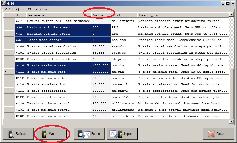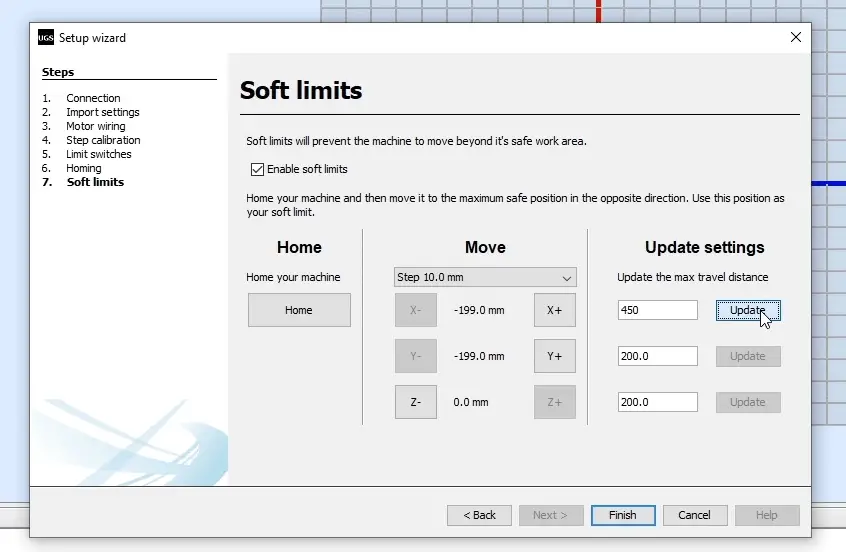

Jog in opposite direction so that limit switch is released. Write down Z position (253.8375mm in this case). Slowly jog Z axis up until Z+ limit switch is hit and machine stops. You will notice that position display now shows all zeros. Now we can execute “Machine/Set Position/Zero” command and set absolute position to zero. Later we will uncheck this to prevent unwanted absolute position change. Because it is usually not good idea to change absolute position make sure that “Machine/Set Position/Enable” is checked to enable these commands. Commands for changing machine absolute position are in menu “Machine/Set Position”. This position should be machine absolute zero. You can just loosely tighten tool in spindle and if accident happens nothing will be damaged. Be careful not to crush tool into machine table when you descent Z axis. Tool is put in spindle and machine is jogged to this position. I will put some tape to mark it so that you will see it better on image. What is important is, that it is always at same position. Usually machine works in relative coordinates and it is not really important where absolute zero is. We need to choose where machine absolute zero position is. This means that we will use them to set machine absolute coordinates. Limit switches can be used as reference switches. All 5 limit switches should be verified like this. When machine stops you should be able to jog in opposite direction. Your hand near moving machine in usually not good idea so keep safe distance. To verify that limit switches stop the machine, jog in direction of limit switch and trigger it with hand. To do this “Limit Switches Stop” checkboxes should be checked. Triggered limit switch should stop machine. To verify that all limit switches are working, trigger switch with hand and position display will become red or purple. Two limit switches on X, two on Y and one on Z axis. Machine that I will use has 5 limit switches. For now it is important that everything is set to zero. “Empty” tool should be selected with with “Machine/Tools/Select/Empty” and tool offset should be set to zero with with “Machine/Tools/Zero Tool Offset” command. Working offset should be set to zero with command “Machine/Offset/Zero”.
#Grbl controller settings how to
If your SPU is not yet set please read SPU tutorial: How to set Steps Per Unit values?įirst we need to set offsets to zero. If position display changes for 100mm then machine should move 100mm. You should verify that distances in all directions are correct when machine moves. “Steps per unit” settings are already calculated and set.


I use metric (millimeter) units but everything is same with imperial (inches) units except numbers are different (1mm is apporximately 0.03937in). I will use my router machine as an example but you can do it similar way on all machine types. Gearing and half-stepping is for the next planned generation of SCARA.I will try to show you how to setup your CNC using PlanetCNC software.How to solve? Gearing and half stepping, PID, or physical damping? This is seems to be a common theme!, and micro-stepping does not help (makes it worse). The arms suffer badly from under-damped motion. The controller seem more quiet but hard to tell. Nothing to do here (I think), the spindle speed range is 0 to 1000 (i.e.
#Grbl controller settings drivers
The stepper drivers where set (hard-wired) to 1/16 micro-stepping.
#Grbl controller settings full
The stepper motors are 0.9 degrees per full step. It confused me as I am used to the motors staying on. Surprisingly GRBL did not work "out of the box", Basically, "$1=25" shut down the motors after doing a move. I am currently using a 12v 2.5A plug pack but I suspect this will be inadequate for both the motors (0.64A per phase, there are 4 phases) and the Laser (1A). It has a built in power on/off buttons which are quite handy:Īs my laser module has a built in power supply and only needs PWM, but this gives you the idea: Here is the controller I am using (except my is covered with labels): I thought I would buy the latest Laser CNC controller as I would like to use grbl v1.1 (my old Laser uses grbl v0.7 and is not compatible with later grbl versions). The latest is v1.1, in this version the spindle on/off and spindle speed (PWM) pins have been swapped.

I have an old Laser controller but it only supports grbl up to v0.9. But I intend to convert a cartesian gCode file into a format that will fool grbl. Grbl does not have native support for SCARA.


 0 kommentar(er)
